


When automation fails, proximity sensor testing is key. This guide covers test methods, interpreting sensor symbols on schematics, and 5 proven troubleshooting steps to quickly restore your production line.
When the industrial automation system suddenly stops working, troubleshooting can’t avoid checking the sensor. Testing the proximity sensor is the fastest way to determine whether the device only needs to be adjusted quickly or needs to be completely replaced. Regardless of the needs of the manufacturing industry, the automotive industry or the security system, it is necessary to understand how to diagnose proximity sensors.
In the guide, we’ll detail how to perform proximity sensor test, how to properly interpret proximity sensor symbols on schematics, and 5 proven troubleshooting methods to get your automated production line back up and running.

Determine Your Proximity Sensor Types
Proximity sensor is a non-contact electronic device used to detect the presence or absence of objects within a specific range. Main sensor types:
- Inductive proximity sensor: metal objects can be detected without contact.
- Capacitive proximity sensor: Can identify non-metallic objects and measure material density. They are commonly used in material handling area and liquid level measurement.
- Ultrasonic sensors: emit high-frequency sound waves to measure distance and detect clear, transparent objects.
- Photoelectric sensor: object detection, distance detection and unmanned detection using light.
If you want to know more about the complete sensor types, please read:
Common Proximity Sensor Types Used in Industrial Applications
Recognize Proximity Sensor Symbols
One of the biggest obstacles in troubleshooting industrial sensors is reading circuit diagrams. If you don’t know how the device is connected to the PLC, it is impossible to effectively test the proximity sensor.
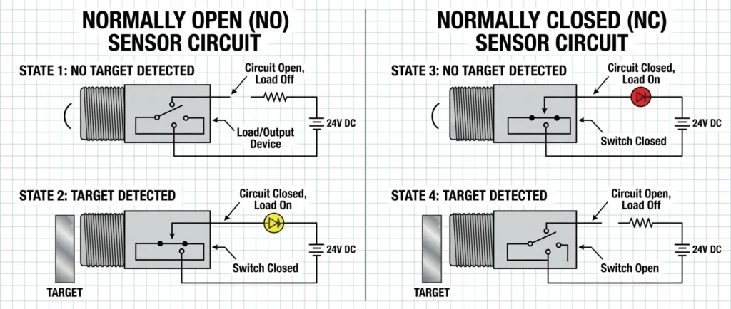
The schematic symbol of the proximity sensor is usually depicted as a diamond with two parallel vertical lines inside, which is used to vividly indicate the existence of the sensing gap. Depending on the wiring method, the symbol indicates whether the sensor is NO or NC, and whether it uses NPN or PNP logic.
| Proximity sensor symbols guide table | ||
|---|---|---|
| Sensor Type | Common Schematic Symbol Features | Typical Application |
| Normally Open (NO) | Gap shown between the contact points; closes when the target is detected. | Activating an alarm when a part arrives. |
| Normally Closed (NC) | Line drawn across the contact points; opens when the target is detected. | Stopping a machine for safety when a guard opens. |
| PNP (Sourcing) | Arrow pointing away from the base in the transistor diagram. Provides positive voltage. | European & US standard PLC inputs. |
| NPN (Sinking) | Arrow pointing toward the base in the transistor diagram. Provides a ground path. | Asian standard PLC inputs. |
Why Does the Proximity Sensor Fail?
Before taking out the tool to troubleshoot the proximity sensor fault, it is necessary to identify these possible causes of the fault.
- Physical damage: The sensor head is subject to an external impact.
- Cable and line problems: Vibration leads to wire wear or loose connections over time.
- Environmental pollution: The surface of the sensor accumulates heavy oil, metal chips or dirt, resulting in reading errors.
- Improper target distance: the sensor is removed from the bracket due to vibration, making it beyond the optimal sensing range.
- Power fluctuation: Voltage spikes damage the internal solid-state circuit.
If you encounter any of the above problems, it’s time to enter the actual troubleshooting phase.
Perform Proximity Sensor Test
Preparation tools:
- A high-quality digital multimeter
- Oscilloscope helps to visualize the sensor’s output model
- Test target object
- 24V DC power supply
- Insulated screwdriver and safety gloves
The following are 5 effective troubleshooting methods used by professional and technical personnel to diagnose sensor faults.
1. Visual inspection and LED indicator light inspection
Turn on the machine power and manually place the target object in front of the sensor surface. If the LED indicator light is not on, it may be a power problem or sensor damage. If the LED indicator lights up but the PLC does not detect the signal, the problem may be in the line or the PLC input card itself. In addition, please check whether there is fouling accumulation on the surface of the sensor and wipe it clean with a dry cloth.
2. Sensor position inspection and measurement range determination
Sometimes the sensor itself is not damaged, but it senses the wrong object. For example, the sensing range of the inductive proximity sensor varies according to the type of metal being detected. Relocate the sensor closer to the target using threaded mounting nuts. Each proximity sensor must work within its specified detection range. If the sensor starts to work reliably, it indicates that the problem may be the existence of obstacles and measurement range.
3. Using digital multimeter voltage test
Three-wire sensor operation steps: the premise is that the multimeter is set to DC voltage. Then the black probe is connected to the blue line, and the red probe is connected to the signal output black line. For PNP sensors, you should see the voltage jump from 0V to the supply voltage (usually 24V). If the voltage is almost unchanged or the reading is a floating value (e.g. 2V or 3V), the internal switching transistor of the sensor may have burned out.
4. Check the line and power supply
Power supply drop is a common cause of intermittent faults in sensors. The input power between the brown line (24V) and the blue line (0V) is measured. Ensure a stable 24V voltage. If the voltage is too low (e.g. 18V or voltage fluctuation), check the main power supply. Don’t forget to check the power connectors, which often have pins bent or water ingress.
5. Use oscilloscope to detect signal noise
If your sensor is unstable, you may encounter electrical noise or ‘jitter’. The oscilloscope is connected to the output signal line to observe whether the clean band appears when proximity sensors are turned on and off. If there is jagged spike or EMI on the screen, it is necessary to use shielded cables or keep the sensor cable away from the high-voltage AC motor driver.
Different Test of NPN and PNP Proximity Sensors
One of the most common misconceptions when conducting comprehensive proximity sensor testing is to confuse the working principle of NPN and PNP sensors. Although they may look the same, their internal logic requires a completely different multimeter measurement position during troubleshooting. To avoid mixing test methods, the following details are given according to the logic type and how your test method must be changed:
| Different testing methods for NPN vs. PNP Sensors | ||
|---|---|---|
| Testing Feature | NPN Sensor (Sinking Logic) | PNP Sensor (Sourcing Logic) |
| Output Behavior | Connects the signal wire to Ground (0V) when triggered. | Connects the signal wire to Positive (+24V) when triggered. |
| Red Multimeter Probe (+) | Place on the Power Supply (+24V / Brown Wire). | Place on the Signal Output (Black Wire). |
| Black Multimeter Probe (-) | Place on the Signal Output (Black Wire). | Place on Ground (0V / Blue Wire). |
| Expected Test Result | Voltage jumps from 0V to 24V when target is present. | Voltage jumps from 0V to 24V when the target is present. |
How to test the 2 wire proximity sensor?
The 2 wire sensor is connected in series with the load. To test it, set the multimeter to measure the current or to measure the voltage drop on the load. When the sensor is triggered, the circuit should be closed and the current will flow to the PLC or relay.
Can the multimeter accurately test the inductive sensor?
Yes. By using a DC voltage setting and measuring the voltage of the output line relative to the ground (for PNP) or the positive electrode (for NPN). The standard multimeter will clearly show whether the sensor’s internal switch is turned on and off correctly.
Why is my sensor indicator light always ON?
When indicator light is always ON, it may be because the internal short circuit causes the sensor to jam, or the sensor installation position is too close to the metal background. Please remove the sensor from the bracket; if there is no occlusion in front of the sensor, the indicator light is still on, indicating that the sensor has been permanently damaged and must be replaced.
Conclusion
Mastering proximity sensor test methods is critical for maintenance engineers and technicians. By learning how to interpret the proximity sensor symbol, verify the power supply and check the target distance, the diagnostic efficiency is greatly improved.
Before conducting any electrical testing, be sure to cut off the power supply of the equipment, ensure safe operation, and use a multimeter for testing.
If the sensor cannot work normally after the above 5 standard tests, it is recommended to replace it with Gtric superior quality proximity sensors to restore the stable operation of the automation system.