


Selecting correct NPN vs. PNP sensors is critical for industrial control compatibility with PLCs. Misuse causes system failure, short circuits, or hazards.
In the application of industrial control panel design, automation equipment upgrade or factory workshop fault investigation, the correct selection of proximity sensor type is the key to realize reliable signal transmission and system stability. As the most basic output configuration of industrial proximity sensors, NPN and PNP are directly related to the compatibility of sensors with control systems such as PLC. Misuse will lead to communication failure, besides also may lead to electrical short circuit, equipment damage and even security risks.
This guide will elaborate on the essential difference between the Sourcing and Sinking sensors in transistor switching logic. And master its selection principles in different industrial applications to help you use each type appropriately in industrial applications.
What are NPN and PNP Sensors?
The difference between PNP and NPN transistors is reflected in their internal semiconductor material structure. The transistors of the two are composed of three layers of semiconductors, the middle layer is the negative (N) material, and the two outer layers are the positive (P) material: forming a P-N-P structure. In contrast; the NPN transistor is a positive (P) material layer sandwiched between two outer negative (N) materials: forming an N-P-N structure. Although the structure is different, both types need to be connected to the positive and negative power supply, and form a complete circuit through the load. Common loads include relays, indicator lights, PLC and other industrial automation facilities.
What are PNP (Sourcing) Sensors?
The ‘Souring’ sensor outputs positive voltage. In a typical 24V DC industrial system, when the PNP sensor is triggered, it connects the +24V DC power supply to the output line. The current flows out from the sensor into the PLC module.
What are NPN (Sinking) Sensors?
The role of the ‘Sinking’ sensor is just the opposite. It does not provide positive voltages, but provides negative circuits (grounded or 0V DC). When the NPN sensor is triggered, it connects the output line to the common end of the negative DC. In this case, the current flows out from the PLC input and down through the sensor into the ground wire.
The Difference in NPN vs. PNP
The sourcing and sinking types are directly related to the bipolar junction transistors used in the sensor circuit.
- PNP = Sourcing (switching positive voltage)
- NPN = Sinking (switching negative voltage)
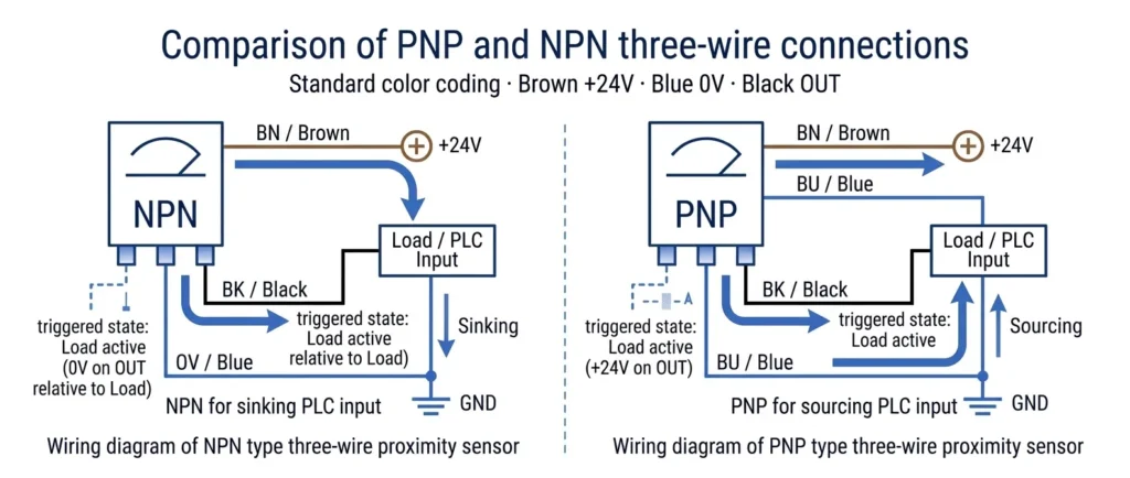
When using a PNP sensor, the load is permanently connected to a negative power supply (0V). The PNP transistor acts as a switch on the positive side. While the proximity sensor is triggered, the transistor is closed, pushing the + 24V voltage along the signal line to the load.
When using the NPN sensor, the load is permanently connected to the positive power supply (+24V). The NPN transistor acts as a switch on the negative side. And the proximity sensor is triggered, the transistor is closed and the 0V (or ground) circuit is connected to allow the current to flow.
| NPN and PNP Reference Comparison Table | ||
|---|---|---|
| Feature | NPN Sensor (Sinking) | PNP Sensor (Sourcing) |
| Internal Transistor | NPN Transistor | PNP Transistor |
| Signal Output State | Connects output to 0V DC (Ground) | Connects output to +24V DC (Positive) |
| Current Direction | Current flows into the sensor | Current flows out of the sensor |
| Required PLC Input | Sourcing PLC Input Module | Sinking PLC Input Module |
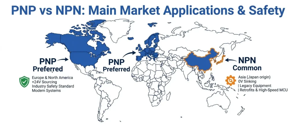
| Common Region | Asia (Historically) | North America & Europe |
| Safety in Ground Faults | Less safe (Can trigger a false ON) | More safe (Blown fuse, fails safely) |
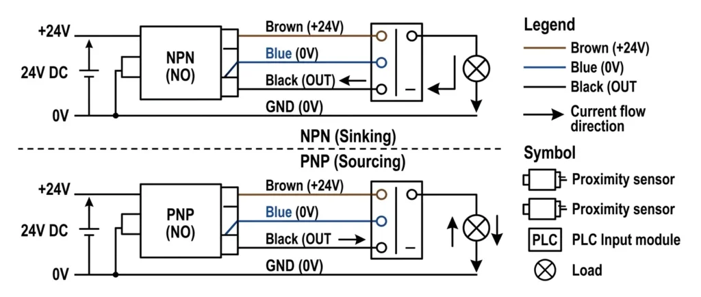
3-Wire Connection of PNP and NPN Sensors
Standard industrial proximity sensors usually use three-wire configuration. The standard color code of the industry is:
- Brown wire: +24V DC (positive power supply)
- Blue wire: 0V DC (negative / grounding power supply)
- Black wire: Output signal line
When triggered, the black wire of the PNP sensor outputs +24V. You need to connect the brown wire to the positive electrode, the blue wire to the negative electrode, and the black wire to the sinking PLC input.For the NPN sensor, when triggered, the black wire will output 0V. You need to connect the brown wire to the positive electrode, the blue wire to the negative electrode, and the black wire tuned to the sourcing PLC input.
When to Use PNP?
In modern industrial automation, PNP sensors are often the first choice for North American and European output.
Why Use PNP for Security?
The primary reason is based on the design principle of fail-safe wiring. When the sensor output line is accidentally short-circuited with the machine metal frame (grounding), the PNP circuit will immediately achieve safe disconnection. Then blow the fuse or let the circuit breaker trip, thereby stopping the machine operation. At this time, the PLC input voltage drops to 0V, and the system is recorded as ‘OFF’ state. Since the PNP logic sensor has the ability to fail safely under fault conditions, it is widely recommended as a standard configuration scheme for industrial proximity sensors.
When to Use NPN?
NPN logic sensors are widely used in most parts of Asia, largely because of the early Japanese electronics manufacturing industry’s extreme preference for NPN logic (NPN transistors have early advantages in speed and efficiency).
Usually you will use NPN sensors in the following cases:
- You are repairing an imported machine that already uses NPN logic and needs to replace damaged sensors.
- The existing PLC input card is wired as a ‘sinking’ module, which means it needs to output current to the NPN Sinking sensor.
- You ‘re dealing with some high-speed microcontrollers or custom printed circuit boards (PCB) that themselves switch to a grounded state.
Summary
The core of the discussion about NPN vs. PNP is to fully understand the practical application, equipment compatibility and factory electrical safety.
The +24V positive signal is sent to the PLC input terminal using a PNP sensor. In the design of modern automation system engineering, this configuration is established as the most safe and widely adopted industry standard, especially for applications with strict requirements on fault safety performance.
The NPN sensor is used to pull the signal down to 0V ground and dock with the PLC input end of the sinking type. This configuration is common in the previous system technical transformation, and it is also the industry standard configuration followed by many Asian manufacturing equipment.As a professional partner in the field of industrial control, Gtric is committed to providing high quality and reliable industrial proximity sensors for automation projects. The product is fully compatible with the traditional NPN system and the modern PNP security control network, and accurately matches various hardware requirements. You could visit gtric.com to explore comprehensive sensor and automation solutions to help the production line achieve continuous, stable and efficient operation.